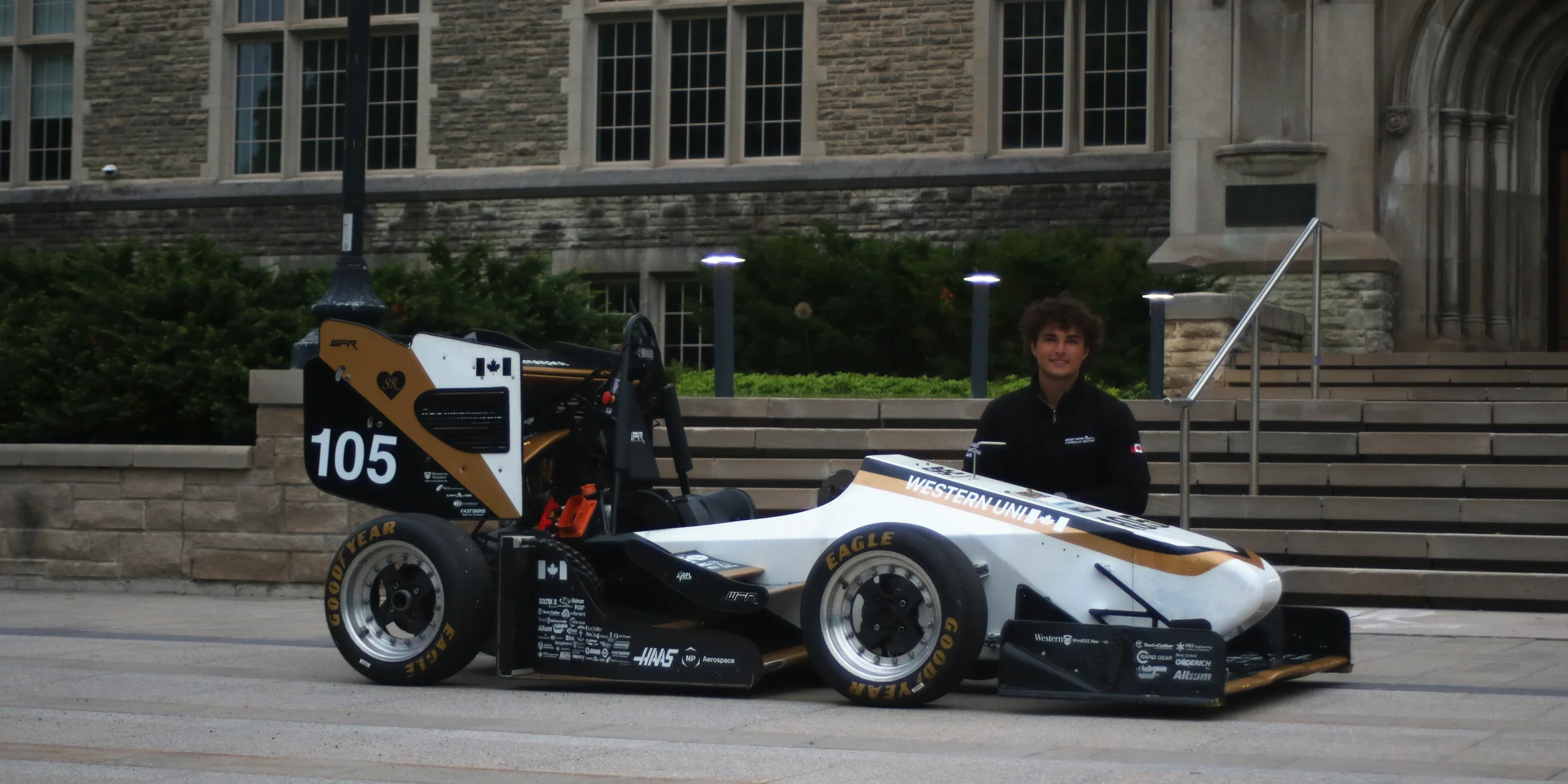
The cause was traced to brake line crimping, so for 2026 the lines were crimped and flared by the manufacturer of the tubes rather than in house.

Subsystem 03 of 13
Brakes & Pedals
Focused on precision and reliability, all components selected to ensure reliable stopping power and optimal driver control.
Our capabilities
- Pedal ratio
- 3.67
- Rotors
- Free floating ASTM 80-55-06 nodular cast iron
- Calipers
- 4-piston front, 2-piston rear
- Master cylinders
- Tilton 78-700, 0.700 in bore
Brakes & Pedals
Features
- 01
Outsourced brake lines
Lines crimped and flared by the tube manufacturer to remove the air and pressure losses of previous years.
- 02
Mechanical bias bar
Kept over electronic bias for simplicity, to tune for track, tyre and driver.
Changing for 2027
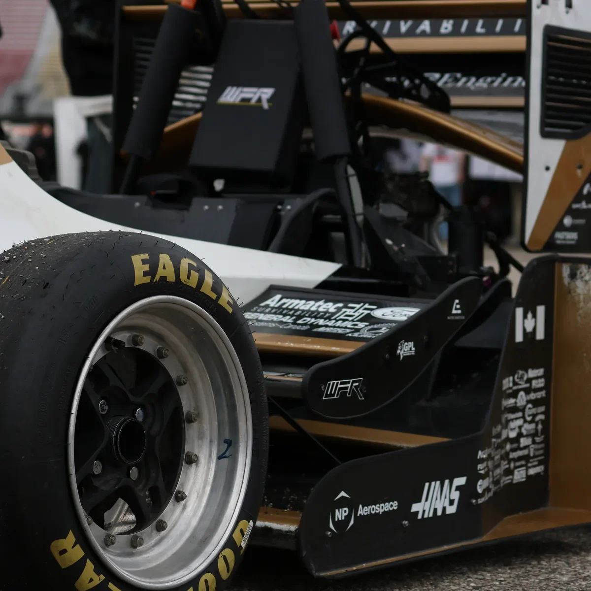
In the making
How it works
Bias is set mainly by the 4-piston front, 2-piston rear split, with a mechanical bias bar kept for tuning.
Ductile cast iron was kept for its thermal capacity and predictable wear: a lap simulation put the front rotors at 500 to 550 degrees C, well below where the iron starts to fade. The car locked its brakes at the New Hampshire competition.